Schematic diagram
Both buses are half-dublex bi-directional, thus the adapter must be bi-directional. In order to prevent signal loops the circuit has mutual exclusion in signal switching. Signal from one direction disables signals going to another direction.I2C bus is active low ans RS-485 has active high, thus signal levels are inverted. This is done by NOR-gates. First NOR-port (IC2/1) is considered as an inverter with enable signal. Input signals of second NOR-port (IC2/2) are connected together, making the port work as a normal inverter. TTL-RS485 conversion is made by industry standard RS-485 tranceiver, there are plenty of manufacturers offering interchangeable parts [4].
I2C bus has two signals: data and clock, thus the circuit in figure 1 must be dublicated in the actual device.

Figure 1. One half of the circuit.
Components
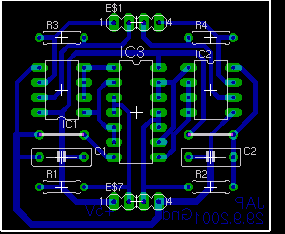
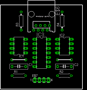
IC1  MAX485 / LTC485 / DS485 / SP485 / ADM485 / SN75167B / etc
       RS485 tranceiver
IC2  74LS33 Quad-NOR, Open-Collector
R1   2,2 kOhm resistor
R2   220 Ohm resistor